Filler Cap

The 'Aston' style fuel filler cap had already been test fitted and the holes drilled in the wing recess to accomodate it.

What I hadn't checked before drilling these holes was where the screw on cap would sit once it was screwed tight. Luckily the position can be changed by adding or removing some of the thin gaskets supplied with the cap so it can all line up properly.

One thing I didn't like was they way the bottom section of the filler cap sits directly onto the body of the car so I decided to fabricate a small rubber seal/gasket out of some rubber sheet I had sourced off eBay.

This gives the whole thing a much better fit and allows the cap to be screwed down nice and tight.


An earth cable has been fitted to the underside of the cap using a connector attached to one of the fixing screws and running this into the main body loom earth circuit.

Undertray

Something I started a week or two ago but didn't get around to updating on the blog was fitting the under tray.

I had decided, in my infinite wisdom, to completely remove the radiator when fitting the body as opposed to just loosening the top mounts as recommended by GD. The one advantage of this was that it was easier to fit the under tray this way. I had marked the position of the radiator bottom fixings and cut a slot in the under tray to to allow this to slot into place. Its then pretty much an interference fit under the front of the nose lip. 

As with all build jobs the tray didn't fit first time of asking. As I have decided to fit my fans on the front of the aluminium radiator the support bars foul the undertray so this needed a big of cutting with the Dremel to allow it to fit.

Twin fans mounted to front of upgraded aluminium radiator
Undertray cut around fan fixing bolt (both sides)

Once this was all in place the sides of the undertray can be left as they are or fixed to the inner wings. I prefer the idea of fixing to wings but there is a big gap between the wing and the undertray both sides and the rear of the undertray is much lower than the bottom of the inner wing (see photo). As it was getting late I decided to come back to this another time.

Note gap between undertray and inner wing and relative height of both parts


Screen

The next big job to crack on with is fitting the windscreen. This seems to be a job that once completed will allow me to get on with a bunch of other tasks too, such as the dash support, dash under trays, dash wiring and fitting the steering column.

As the body isn't fully prepped and polished, I thought it would be best to finish off the scuttle prior to fitting as it would be easier than trying to polish around the screen once fitted.

Right back at the start of the build I had invested in a DA Meguires polisher and some Farecla cutting compound and polish so it was time to try it out.

I had rubbed down the scuttle using 600, 800 and 1200 grit wet n dry paper and had hoped that the polisher would do the trick from this point but I was still able to see some fairly deep looking scratches, particularly in the black stripes. Thanks heavens I didn't have a black car.

Using the DA for the first time
As this hadnt worked as well as I hoped I had read that the Farecla can be used wet or dry. So i wet the head of the DA and went to work... This was the next of my cock-ups!!! With no bonnect fitted the polish was sprayed all over the place including all over me and the engine. Yet more cleaning will be required now :(

Using DA with a wet pad - very messy!!!

To make matters worse the damn scratches were still showing. I will now need to order some more wet n dry of finer grades before trying again.

Oil Cooler 2

Having had a word with Andy at GD, I ordered a fixing kit off him for the oil cooler radiator.

This comprised of a stainless steel plate/bracket and a bunch of nuts, bolts and spacers.

Thought this would be a fairly quick job, so I decided I would fit it today but when I had a closer look it was yet another job that needs some tweaking.


The spacers seem redundant as the top of the oil cooler is already above the level of the bottom of the mouth of the car, the bracket seems to fit at an upward angle not flat and the small fixing holes need to be re-drilled in the correct position.

Once for another day given I'm a little short of time.


Bonnet Scoop 2

The task for today was to finally cut the hole for the bonnet scoop.

Having already established that the oval filter wouldn't fit without some modification, I had trimmed down the air filter mounting ring by about 10-15mm which was more than sufficient to allow the scoop to fit.

After putting the scoop in place, I taped it firmly in place and using a china-graph pencil I marked the outline of the scoop on to the bonnet. I then marked another line inside this to allow for the flange of the scoop before taking the Dremel to the bonnet. At this point my trusty co-builder, Ali, asked me how much a replacement bonnet would cost!!!! Oh he of little faith.

Scoop taped in place and outline marked
And there it is... a whopping great hole

So with the hole cut in the bonnet it was the moment of truth - would the filter fit and not foul the scoop.

Fits like a glove
Next up the scoop needed taping back in place and the holes drilling for the button heads to pass through. Research had shown me that 27 screws is an ideal number which meant 13 either side of the centre screw. To ensure that they are equally spaced, I did all my calculations to determine the distance between centres and then made a little template (see pic below) which I found helped no end.


Template made to ensure holes are correctly spaced
Template ensures holes are correctly spaced

The holes were all drilled using a 3.2mm drill (I am using M4 button heads to fix the scoop in place) and then an M4 tap was run through the scoop and the bonnet, which had now separated into two separate skins. After tapping the first few holes it didn't appear to be adding any value so I ditched this idea and re-drilled them all with a 4mm drill.

Andy had advised that polyurethane (something like no more nails) is a good product to bond the two skins back together. So 'Unibond No More Nails' was applied and I used clothes pegs to hold the two skins in place as I didn't want them pulling too close together.


Now for some reason I just couldn't get the two skins to bond. I suspect the temperature in the workshop was too low as its unheated. Also when I had been running the drill through the bonnet it had caused the gel coat to breakout in a number of places which looked really messy. Needing to fix this and wanting to do something with the underside of the scoop which comes out of the factory with just the rough fibreglass finish with no gel coat,  I decided to call upon the help of Stuart at Carsmetic (he's the guy that filled and sprayed the bulkhead for me).

He agreed to fill the gap between the bonnet skins, repair where the gelcoat had broken out, skim the underside of the scoop with filler and then spray both the underside of the bonnet and scoop. Hopefully when this comes back it will look as impressive as the bulkhead.

Bonnet Catches

Having made a start on the bonnet scoop, I decided I should also get the latches fixed in place prior to fixing the scoop. I figured that by doing this first I had fixed datum points from which to work.

Marking the position of the latch is pretty straightforward, and I followed the instructions on the build CD, marking the centre lines as directed.

Masking tape applied to allow centrelines for bonnet latches to be marked

Once the centre lines were marked it was a simple case of drilling through the bonnet a hole the same diameter as the latch body. Or so I thought...

The latch itself has two lugs to prevent it from turning within the bonnet as well as the two fixing holes. Now drilling the fixing holes was easy as the position was simply taken from the mounting gasket. I then used the Dremel to cut slots for the lugs but it seemed no mater how I did this the damn latch would still not fit. Eventually after much drilling, cutting and offered up the latches I had a hole in the bonnet that worked albeit not a very pretty hole. But once the latch was fitted in place it looked fine.

Bonnet latch fitted

Now that the latches were in place I needed to cut the slots in the bulkhead to accept the locking mechanism. Marking the position of these slots isn't explained in the build CD and I didn't find much advice in any of the other blogs I'm following so I was running blind on this one.

First off I decided to mark the centre of the slot relevant to the centre line of the car (made easier by the fact I have twin bonnet strips moulded in). Effectively this is in the same position as the centre of the latch. Then I marked a line from here to join the two centre lines together. This then gave me a position at the top of the bulkhead from which I could mark a line down vertically using a spirit level.

I then just needed to decide on a suitable distance down from the top of the scuttle. I decided it would be best to leave this as short as possible thus reducing the amount of flex in the latch shafts. Fortunately, at this point I also realised that the slots needed to be cut parallel to the top of the scuttle and not horizontal.

In order to get the slot the right size I put the escutcheon in place and marked around this. Knowing I could then open the slot up and reposition the escutcheon to suit at a later date.

Escutcheon being used as a template
Finished slot

Once the slot was finished I was then able to close the latch and establish how much adjustment would be required to get the bonnet to sit at the same height as the scuttle.


Bonnet latch closed. Needs adjusting for correct shut height

Door Edges

Another job that has been hanging around unfinished is trimming the door edges to give a uniform 12mm lip for the sealing rubber to be attached to.

Not having any dividers available, I improvised using the method recommended on other blogs, ie. I took two pieces of wood and banged a nail through the one piece 12mm below the edge of the other piece. This was then used to scribe a line on the door lip. I then took a pencil and ran this along the scribed line to give a nice clear line to cut to.


Line marked 12mm from door edge, part trimmed

Once this had been done I fixed the rubber seal in place to see how the door felt when being closed and I have to say I was delighted with the result. Juts need to sort some springs for the door handles now so they move back into position after opening.


Door seal in place

Bonnet Scoop

With the body now on the chassis, it  was time to refit the bonnet and establish whether or not I could get my 'Cobra Style', oval air filter to fit beneath the scoop.

After taking some initial measurements, I was hoping that by positioning the scoop about 10-15mm further forward there would be sufficient clearance. My other option to make more room would be to reduce the thickness of the plastic ring that fits between the carb and the filter.

Before making the big cut for the scoop I established the centre position of the air filter and then transferred this position onto the bonnet. 

Bonnet marked with centre of air filter

Then using the circle cutting tool on the Dremel I cut a hole slightly larger than the air filter mounting ring.
Hole cut slightly larger than air filter mounting ring
Bonnet in position showing air filter mounting ring fitted to carb with mounting stud in place

From here I positioned the scoop in place and lowered the bonnet to see if the top of the mounted stud would clear the underside of the scoop. As it happened it cleared by about 2-3mm. Unfortunately, no matter what I did with the scoop positioning, the front of the filter fouled the scoop lifting it from the bonnet.

Air filter mounting stud just clears underside of scoop

As it was getting late I decided to call it a day at this point. I had learnt form previous experiecne that any cutting or hole drilling should be done while feeling fresh and not when tired and frustrated as this


Body Mounting 3

Having got the body pretty much on and the mounting holes lined up with bolts part way in last week, it was time to do the final fit which involved fitted the rear mounts and drilling holes to fit the mounts that go through the inner wing. These hadn't been fitted before as the original holes had been filled when I had the bulkhead and engine bay sprayed.

At this point the car was jacked up and put on axle stands, now looking every bit like a real car :)


The wheels were then removed for the first time. When we came to remove the front left wheel we couldn't budge the spinner (and yes I know its a reverse thread) but it wasn't for shifting easily.

In the end I took a larger hammer and a large piece of wood to protect the spinner and gave it another whack. This time is simply fell off in one piece, the bolts securing it to the actual wheel hadn't been tightened up and had been cross threaded.

Damaged thread on the spinner adaptor

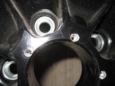
Corresponding damage to the road wheel

After this we did a check of all the others and it turned out none of the adaptors had been properly tightened. The damaged threads were re-tapped and all is now well but this is certainly something to check if you are using wheels like mine with decorative spinners.