Roll Hoops

Wanting to get the car finished by the end of May, I'm throwing some extra hours into the project at the moment and I took the day off with the plan being to fit the roll hoops.

I wanted ot do this when I was feeling fresh and not after a long day in the office and I wanted to make sure I had plenty of time in case things didn't go according to plan.

Opinions and techniques for fitting the roll hoops vary form the plumb line method as used by the factory to a steel rod and template set up as I believe created by Steve R. Time taken by other builders to fit them also seems to vary greatly and I  must admit to being somewhat nervous about starting this task.

Before starting, I had a good chat with Alan GD who explained how to set the car up level and then how to use the plumb line method. I had already sourced some 12mm threaded bar and some plywood to make template but after listening to his advice and discussing/arguing with my co-builder Ali I decided to go with the factory method.

With a method agreed, I started to look at how to physically implement the plan and it became clear I was going to need a new drill or at least a 90 deg angle chuck for my existing drill as its too big to get in the confined spaces inside the boot. I managed to find a suitable attachment in stock locally at Screw Fix but this wasted a whole lot of time and it was nearly lunchtime by the time I actually got started.

However, after a full afternoon I had got both roll bars trail fitted. Admittedly, they still need to be filled with expanding foam (apparently this helps reduce road noise from being transmitted up from the chassis), bolted up in place and then the holes in the scuttle tidying up and rubber gaiters fitting but the bulk of this daunting task is behind me.

The following summarises the method I used.

1. The car was jacked up until it was level both front to back and left to right.

2. The rear wheels were removed for access

3. The rear coil spring retaining bolt was removed so that I could get access to mark the position of the outer leg mounting hole


4. Having marked through the holes in the mounting brakets for the front two legs small pilot holes were drilled through from under the boot. The same was then done for the rear leg (although this position is flexible to a degree as the bracket can swivel left or right a little.

5. I then used a hole saw of similar diameter to the legs to open up the lower pilot holes. This gives a clear view of the mounting holes.


6. A plumb line was then taken from the centre of the mounting hole and the position marked on the underside of the rear scuttle. This is a little tricky but lying in the boot helps!!


7. Pilot holes were then drilled into the top scuttle from the underside. These holes were then checked for accuracy by running the plumb line all the way through the hole. A couple were a little bit out so were re-drilled. Then the holes were opened up with a hole saw and dremel.


8. The roll hoops were then passed through and positions checked by running the fixing bolts into place. 


After all that it was time for a cold beer...

Next time I will tidy up the holes, fill with foam and fit the rubber gaiters. Need to read up on what people do for sealing the lower holes and then look at getting the carpet in as the roll hoops pass through the carpet in the boot and they cant be bolted in place until this is done.


Boot Lid

One thing I haven't got  around to sorting out yet is the boot lid. I had test fitted it some time ago and it looks ok but I thought it was about time to get it finished.

I have read several other blogs and the common practice for fitting the number plate lamp is to thread the wire through the nearside hinge and then drill a hole in the boot lid behind where the hinge attaches and feed the wire through the strengthening rib of the boot lid. Some seem to have more luck with this than others - with some people able to thread form the hinge right the way though to the number plate lamp and others needing an extra hole or two at each corner. My plan was to feed it through as far as the the hole for the boot latch and then feed back up to the number plate lamp mounting position from there.

The boot was marked up and the position for the latch established and a hole was drilled.

This is where the square bar passes through from the handle on the outside to the latch on the inside


So far so good... but it wasn't to last :(


To make matters easier, I followed Ryan's idea and cut the loom close to where the wire passes through the hinge. This would allow me to feed the main wire through with the boot lid off the car and I could later join the two sections using bullet connectors which will be handy if the boot is to be removed again at a later date.

My first attempt was to use a length of wire (an old coat hanger straightened out) but this was too rigid and I had no joy.

I then borrowed a proper fish wire kit of a friend of mine and thought it would be plain sailing now I had the right equipment - how wrong could I have been.

I managed to get the fish wire all the way through but at the last minute (and I still dont really know how it happened) the wire fell backwards between the two skins of the boot lid and got stuck.

No matter how hard I tried I could not free it. I left it for a few days and a couple of colleague had a go at freeing it but still no joy so the only thing left was to drill into the strengthening rib and poke something else back in to free it.

The photo below shows just how many times I tried without success. Now I have to say this is really embarrassing and I had vowed not to list this on my blog but if the blog is to be a true record of my build progress then it needs to be recorded here!!!

Boot lid looking more like a Dalmatian than a Cobra

Even after all this the offending wire remained well and truly stuck (couldn't even see it) but I managed to get a new fish wire in and pulled the number plate wires through.

Fuel Sender 2

Got some M5 button heads in the post today so I fitted the fuel sender into the tank. Will re-fit the tank once I have sorted out all the plumbing required to connect the fixed fuel line from the rear of the chassis to the tank itself.

All this talk of JIC that and Dash the other is like a new language to me :(

Fortunately, I have been able to make contact with Fay at Speedflow and she has been a star in helping work everything out for me.


Steering Column

With the dash and screen support now in place, I was able to tackle the steering column today.

This was another straightforward job and once that when finished made the project look even more like a car!!

The modified column supplied by GD comes in a bare metal finish so this was masked up, primed and then finished in gloss black paint.


The column is passed through the large hole that had already been made in the bulkhead (this did however need a little opening up) and then connected to the screen support bar  inside the car. A 'U' clamp is then used to fixed the column to the chassis. The same sort of grommet as used for the roll hoops is used to make a neat finish.


The column the connects to the steering rack via some UJ's and connectiing rods. These all need bolting up  tight to eliminate any play in the steering once fitted.


A cheap old steering wheel (off a Vectra) was picked up for a tenner off eBay and fitted which will allow me to move the car around a if necessary.


Oil Cooler 4

Having fitted the oil cooler radiator in place, it is time to find a suitable method of fixing the thermostat in place. This is connected on both sides by two thick braided hoses one to the oil cooler rad and the other to the adaptor that fits between the oil filter and the engine.

The thermostat needs positioning so that the hoses don't foul on anything that moves or is hot and the ideal place in on a  bracket mounted to the nearside front chassis members that support the wishbone.

I made a template using thin card held in place then folded around the chassis members. I then cut along these fold lines to create a template that I could transfer on to a thin piece of stainless I had brought off a local stockholder.

The template was cut to size and clamped in place to mark the position of the fixing holes and then returned to the bench for drilling along with the holes required to attach the thermostat to the bracket itself.

Once I was happy with this I then clamped the bracket back in position and drilled pilot holes through into the chassis.


This is yet another job I should have done before the body was on as access was awkward to say the least!!!

After drilling the pilot holes, I then gradually increased the size until I cut fit rivnuts and attached the bracket.


The thermostat was then fixed to the bracket and the hoses attached. Overall I'm quite happy with the set up but I think the front hoses need to be shortened a little as they dont sit quite right at the front of the car. Ideally I would use some 45deg adapters to ease the angle at which the hoses connect but given the price of them I think I'll make do for now!!!!

Job Done


Screen 4

Stuart from Carsmetic has been in and polished the scuttle for me and it looks amazing. There is certainly an argument for getting a professional to do the final polish - he said his job would have been a lot easier if I hadn't caused so many scratches trying to do it myself.

Now this has been sorted I fixed the screen in place for what will hopefully be the last time. Started off by bolting everything back up and checking the rake angle of the screen etc. Then, when everything was tight I removed the screen from the support legs so that I could fill around the gaps where they pass through the body with silicone and then fit the escutcheons once the silicone has dried.


The gap needs filling with silicone to prevent leaks

Dash & Screen Support Bars

Now that I have test fitted my screen and got the holes in the legs in the right place, I could move on to fitting the screen and dash support bars.

This was a simple case of working out which way round they fit and then tightening up the bolts.


The screen support bar also needs fixing to the body. There are two brackets that have to be bolted to the transmission tunnel. The position of these holes were marked, the support bar removed and then rivnuts fitted. The dash support cant be bolted in place until the tunnel carpet is fitted.


With hindsight this is something else that I wished I had done before the body was on the car as I could thenhave got access under the transmission tunnel. I decided to fit the screen with the body on as I was worried it might break when wiggling the body on to the chassis.

Fuel Sender

A week or so back, when I was fitting the fuel tank, I started to have a look at the fuel sender but didn't actually do anything with it, so last week I decided it was time to rectify that and get it fitted as the tank was back out of the car and on the bench waiting supply of fuel line fittings.

The sender unit bolts into the top of the fuel tank but as it is a generic item it has to be amended to suit the Cobra tank. This is a relatively simple alteration which involves setting the length of the wire that attaches the float to the sender itself. The instructions give a number of different dimensions so it was just a case of working out what length my wire needed to be with a minimum tank depth of 295mm.

Preferring to err on the side of caution (I want a zero fuel warning before its too late) I decided to use the shallowest point of the fuel tank when calculating the tank depth. This is 295mm. It is then a case of working out the correct length of wire from the chart. I calculated this as 227mm.

The sender mechanism comes with two wires which have to be trimmed then held togther with clips which have to be welded in place.

At this point, although I had a nice shiny new gas soldering iron I had no gas, so this was left on the bench and finished off today.

Need to find out what size bolts are needed to attached the sender to the tank now and as soon as the fuel line fittings are sorted out the tank can go back in and were a lot closer to a first start.

Soldering the sender wires to correct length

Oil Cooler 3

With a hour left before needing to head home for the day, I decided to fit the oil cooler into the nose section of the car. I could then determine the best fixing position for the thermostat and, if necessary, cut the hoses to a more suitable length.

I had bought a mounting bracket and fixing kit off GD rather than messing about trying to fabricate my own. As usual the holes in the bracket don't quite align with the holes in the cooler so these needed opening up.

To determine the position of the fixing holes which would be drilled in the undertray I marked a centreline on both the undertray and the oil cooler and lined the two up. I fitted the bracket to the top of the oil cooler and put this in place in the lip of the nose cone. I then marked the hole positions and drilled them in place.


NOw the GD fixing kit comes wiht spacers which are designed to be fitted between the undertray and the GRP below. With this in mind, I drilled right the way through the GRP but when I went to put the spacers in place this seemed pointless. The gap between the tray and the GRP was a lot bigger than the spacer and there were only spacers for two of the four fixing bolts.

I bolted everything up in place and to be fair it fits really firm and I cant quite see why I need to fix through to the GRP so I will probably leave this as it is now.


The only thing that needs sorting now is to get a couple more button heads as there were only 6 in the fixing kit and with my method of fixing I need 8. For the time being I have used a couple of socket cap heads to get the job done. No one will ever notice but I will know they don't match so I will have to change at some point - I've noted it on my snagging list.


Screen 3

Had a bit of trouble previously getting the batons to adhere to the car. Reading the instructions on the 'No More Nails' tube I noticed that the ideal temperature should be +10° C. As my workshop has thin aluminium walls and roof and it isn't heated, at this time of year it barely reaches that let alone stay above that.

Eventually, I managed to get them to stick on using a combination of adhesive and silicone. They doesn't need to be to firm as they have to be removed once the holes are marked on the screen legs.

With the batons fixed in place the screen mounting bolts are removed and the screen legs are lowered through the slots in the top of the wings/scuttle. They then pass between the baton and the mounting panel. I decided at this point to get the alignment as correct as I could and then just drill one hole which could be made oversize later if adjustment becomes necessary.


Again, another point to note here is the dimension required to get the screen rake at the correct angle. The build CD says 860mm but most of the build blogs say 930mm. Having spoken to GD, I think the 860 is for a Mark III not a Mark IV.

To get the 930mm right, I trimmed a piece of timber to length and wedged it between the roll of the rear scuttle and the top of the screen. This gives a nice solid point to ensure the other holes are all marked in the right positions.

Timber prop ensures 930mm distance from scuttle to screen top is maintained.

The other thing to get right is the gap between the bottom of the screen frame and the top of the scuttle. I've read about people making up all sorts of spacers to get this right but again with some advice form GD, they suggest that its more about getting the screen to fit with the rubber seal sitting properly on the scuttle. By default, this gives a gap of between 4mm and 6mm at each side once the escutcheons are fitted.

With this in mind I concentrated on getting the gap level each side.

Ensure gap both sides is the same

I also made sure that the screen was sitting 'square' to the car sides. This was checked by measuring from the edge of the screen (I used the outer fixing hole for the sun visor as a common reference point) to top of what is in essence the 'B' pillar.

Once I was happy with this the holes were marked and drilled and the screen was test fitted. The centre support bar mounting bracket was attached and the hole positions marked on the scuttle. With the screen removed these holes were drilled slightly oversize (5mm to accommodate 4mm button heads).

Im still not happy with the scuttle finish despite lots of rubbing down and polishing so I cant final fix the screen just yet but hope to get this done in the next few days as this will hamper progress otherwise. But all in all I'm pretty happy with how it looks :)


Seats

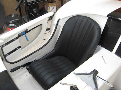
My interior arrived a few days ago and with a few hours spare to work on the car on my own I was looking for something new to do. Well, having a big box of new stuff and not getting to grips with it is like having new toys at Christmas and not playing with them so I decided I would have a look at how the seats and runners all go together.

As soon as I bought a seat into the garage I couldn't resist trying it in the car - just to see what it looked like - I didn't sit in it or anything like that... honest!!!

Just to see what it looks like

The runners are bolted to the underside of the seat using 4 button head screws that come with the runners. These bolt into captive nuts that are hidden under the leather of the seat. Once you know roughly where they are they are quite easy to locate.

I then used a bradawl to open up the leather and expose the captive nut and test fitted the button heads.


The first seat went according to plan but I ran into some trouble on the second seat as the one captive nut was defective. I was unable to repair this using a tap (my tap and die set seems to have a different pitch for M8 to the seat mounting bold) so i drilled a new hole and fitted a rivnut in line with the next position in the runner.


The runners were then fitted without further problem. It looks like the runners I have are of a newer design than on some of the other builds I have looked at as the adjuster bar is easily removable. This is a real a bonus for IVA as I understand the seat needs to be in a fixed position if the head restraints aren't seat mounted.


Couple of tips here...

1. Make sure you put the runners on the right way round, ie. check which end goes to the the front of the seat so that the adjuster bar isn't at the back of the seat.
2. The distance between centres on the seat mountings is 330mm - there is only one way up the runners go using this measurement. The distance between centres for the side of the runner that mounts to the car floor is 300mm - this is a pain as the car floor is predrilled at 330mm.
3. The spacers are used on the front mounting bolts only - no spacers are used at the rear which is contrary to the build CD

Exhaust

The main section of the exhaust has been fitted for sometime now but until the body was on I couldn't fit the rear boxes as these are mounted using the 'cotton reel' style mounting brackets which are bolted through the floor of the boot.

In order to mark the position I put a piece of masking tape roughly in place then pushed the back box up and the head of the bolt marked the masking tape giving the correct point to drill through.


For some reason I havn't taken a photograph of the boxes in place... will update this later

Bonnet

With the scoop in place, the bonnet hinges back from powder coating, it was time to final fit the bonnet.

This would simply be a case of refitting the hinges (I had cleverly marked the one hinge so I knew which one went where - but had rubbed this into off the white board buy the time they came back), refitting the bonnet latches and then adjusting the height as all gaps had been sorted out before power coating.

So the bonnet catches were fitted without problem. The hinges were were fitted to the car (Ali and I were certain that the marked hinge went on the nearside) and the bonnet offered up for fitting to the hinge. The nearside fitted without problem but the offside was a mile out. So the hinges were swapped over and refitted but this time when the bonnet was closed the gaps were all over the place.

Wanting to realign the bonnet without lots of bending and packing of the hinges, I drilled out the mounting holes slightly oversize to give some movement and then put strips of card back in place around the bonnet and tightened everything back up. It looks ok but not 100% happy but rather than waste lots of time trying to sort this now, I want to crack on with the build and come back to this as part of my snagging list.


Card used to correctly 'gap' the panel

Catches fitted and adjusted
Shut height adjusted to bring bonnet in line with scuttle

Cooling System

Another simple task that isn't going according to plan is connecting the cooling hoses between the heater matrix outlets and the water pump and manifold.

Ken at EDA sent me some Speedflow connectors in black to match up with the other fittings using on the fuel line (just find the standard red and blue looks a bit blingy and I want to stick to my black &white/silver theme).

The blanking plugs were removed from the water pump and manifold but the taper thread seems too big, leaving the fitting sitting to high on the pump and then the 45 deg fitting fouls on the alternator adjustor bar.

Also the 45 deg fitting doesn't put the hose at the correct orientation from either the pump or the manifold so need to reassess this next week. Essentially I need to copy the set up used by STR on his iron block engine.

Taper thread doesn't screw in far enough

Fitting fouls alternator adjustment bar

Bonnet Scoop 3

I received the bonnet back yesterday from Carsmetic and Stuart had done a great job of repairing the damage caused where the gel coat had broken through when I drilled the scoop fixing holes. He had also skimmed the scoop and painted it the same colour as the bonnet.

As the scoop fixing holes had been partially filled I decided to apply masking tape to the underside of the bonnet and then to re-drill using the drill in reverse to reduce the amount of breakout. This worked pretty well with just one or two bits of breakout this time. Although not necessary to hold the screws in place as I'm using M4 nyloc nuts, I put some slightly oversize washers on to cover the bits of breakout.

Taped in preparation for re-drilling

Although not necessary to hold the screws in place as I'm using M4 nyloc nuts, I put some slightly oversize washers on to cover the bits of breakout.
Scoop bolted in place using M4 x 20 button heads and M4 Nylocs. Oversize washers hide any breakthrough caused by drilling the holes.

All fitted


Undertray 2

A few weeks ago I fitted the undertray in place but didn't decide what to do about fixing the sides to the inner wing.

After a bit of reading up and some trial and error, I decided the best thing to do would be to use rivnuts at the back of the undertray where the gap is the greatest and then use a self tapper at the front purely for cosmetic purposes.

The undertray is much lower than bottom of inner wing and although it can't be seen in this photo there is about a 10mm gap between the edge of the undertray and the inner

A hole was drilled through the inner wing and into the under tray and then an M6 rivnut was fitted into the under tray. An M6 bolt was then passed through the inner wing to secure in place. A self tapper was fitted at the front of the under tray and then the small gaps that were left were filled with some silicone to keep it all looking neat and tidy.

Undertray held in place with Rivnut and M6 Bolt